
Line-Following Obstacle-Avoiding Car
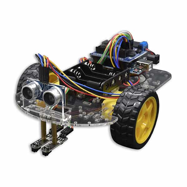
Adds an HC-SR04P ultrasonic sensor to the line-following car, so it can follow a line and avoid obstacles automatically.
What this kit teaches
Assembly and motion control
Getting started with assembly, preparing the tools, soldering the motors and reinforcing the wire ends, removing the protective film from the chassis and installing the auxiliary wheel, installing the encoder discs and DC motors, and downloading and installing the code editor.
Line following and obstacle avoidance: developing with Arduino IDE
Adding line following, adding obstacle avoidance, an introduction to writing Arduino code, and a code walkthrough.
Course outline
01 Assembly (2 class periods)
Unit contents
- Getting started with assembly
- Preparing the tools
- Soldering the motors and reinforcing the wire ends
- Removing the protective film from the chassis and installing the auxiliary wheel
- Installing the encoder discs and DC motors
Related article: Arduino Car Tutorial Series—Unit 1: Assembly
02 Motion control (1 class period)
Unit contents
- Downloading and installing the code editor
- Basic operation
- Adjusting steering
- Advanced operation
Related article: Arduino Car Tutorial Series—Unit 2: Motion Control
03 Line following and obstacle avoidance (2 class periods)
Unit contents
- Adding line following
- Adding obstacle avoidance
Related article: Arduino Car Tutorial Series—Unit 3: Line Following and Obstacle Avoidance
04 Developing with Arduino IDE (2 class periods)
Unit contents
- Introduction to writing Arduino code
- Code walkthrough
Related article: Arduino Car Tutorial Series—Unit 4: Developing with Arduino IDE
This course outline is based on existing CIRCUS Pi tutorial articles. Class period counts are estimates and can be adjusted for your class.
2022 version
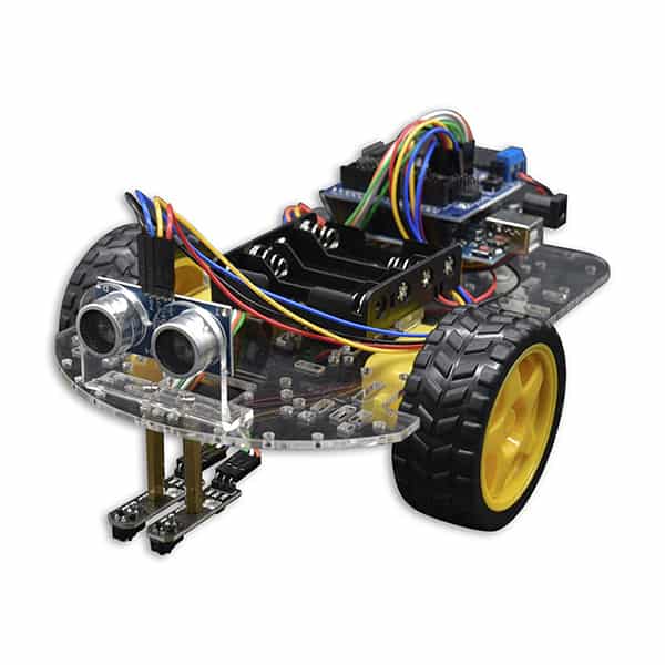
2018 version
Hardware specifications
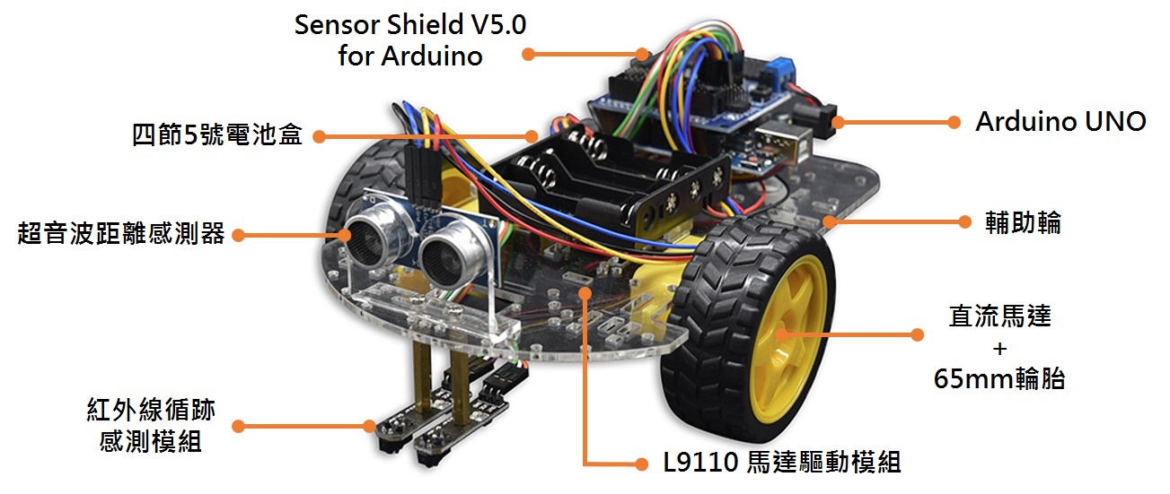
| Item | Qty |
|---|---|
| Smart car chassis kit | 1 |
| UNO R3 Enhanced Edition for Arduino® | 1 |
| Sensor Shield V5.0 for Arduino® | 1 |
| Circus L9110 motor driver module, single board, pin headers | 1 |
| Infrared line-tracking sensor module | 2 |
| TOSHIBA AA batteries | 4 |
| M3 hex fine-thread brass standoff, 10 mm | 6 |
| M3 hex female-female fine-thread brass standoff, 30 mm | 2 |
| M3 colored hex nut | 1 |
| M3 × 8 mm Phillips pan-head screw (colored) | 1 |
| Colored Dupont jumper wires (female/female) with 1P-1P female connectors, 30 cm | 2 |
| HC-SR04P ultrasonic distance sensor module | 1 |
| HC-SR04 ultrasonic distance sensor module bracket | 1 |
• Selected modules
1. Motor driver module
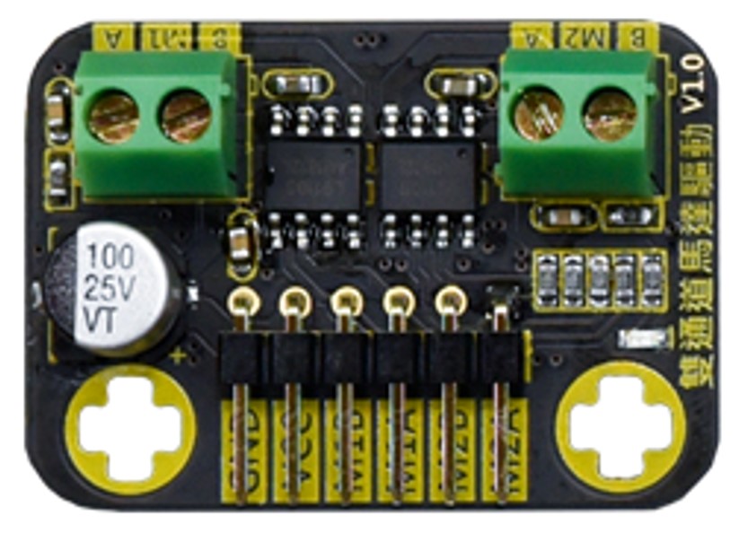
The car’s motors are controlled by the Circus L9110 motor driver module, for stable, reliable operation. It connects to two DC motors. Each motor is controlled by two signal lines: setting those lines high or low switches the motor between forward and reverse, and PWM output controls the speed. External power can be up to 12 V, which suits projects that need drive power, such as cars and electric fans.
2. Line-following module
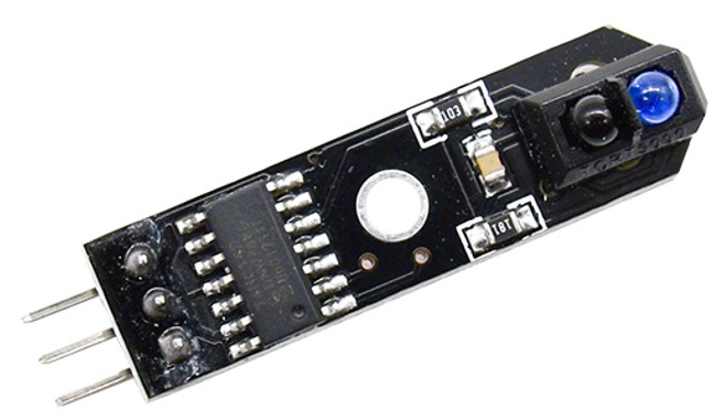
The line-following module uses a TCRT5000 infrared reflective sensor with a detection distance of about 1 mm to 25 mm. The digital signal is simple to use: the output is 0 over a black surface (line) and 1 over a white surface (line), so it easily detects either a black line or a white line. An LED on the back of the sensor module turns on and off with the sensing state (the LED is lit when an object is within detection range), which makes debugging and checking the program logic easier.
3. Ultrasonic distance module
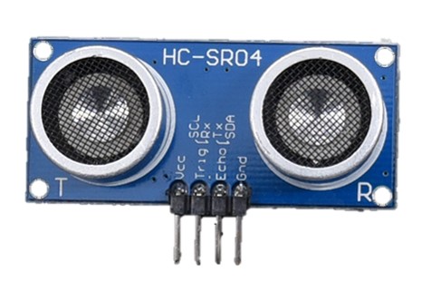
Obstacle avoidance uses an HC-SR04P ultrasonic distance sensor. It works with 3.3 V or 5 V power, with a measuring range of 2 cm to 450 cm (5 V) or 2 cm to 400 cm (3.3 V), a detection angle of less than 15°, and an operating temperature of -20 °C to 80 °C. It is one of the most commonly used sensors for obstacle-avoidance projects.
• Flexible expansion
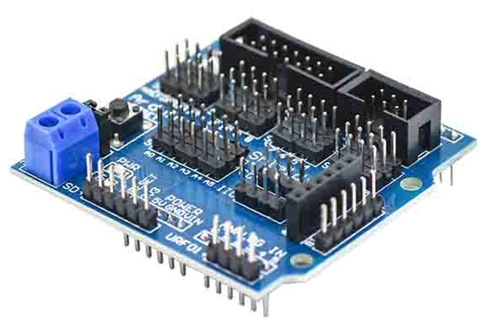
The Arduino Sensor Shield expansion board stacks directly on top of the Arduino UNO. It extends all of the digital and analog pins and has dedicated ports for I2C, UART, and Bluetooth. The function pins are laid out alongside power pins, which makes it easy to connect sensors and servo motors. The board has a socket for connecting the battery holder’s power cable, plus a power indicator LED and a Reset button.
Video
Contact us
Your message goes straight to our team, and we usually reply within one business day.
- 01Questions? Send us a message or add us on LINE.
- 02Quotes and orders, including international shipping
- 03Teacher training and professional development

Scan with your phone to add us on LINE.
Add us on LINE